Catalog
LED Warning Lights are an important part of modern vehicle visibility systems used on emergency, utility, construction, agricultural, roadside assistance, transport, industrial, and specialty vehicles. Their role goes beyond producing bright flashing light. A properly designed warning system must communicate a vehicle’s operating condition clearly while working with the vehicle body, electrical architecture, mounting position, optical requirements, environmental exposure, and applicable regulations. Light color, beam distribution, flash pattern, synchronization, housing construction, and controller design all affect how effectively a warning signal is perceived. Understanding these factors helps vehicle manufacturers, fleet operators, integrators, and equipment designers develop warning systems that are practical, durable, maintainable, and appropriate for the conditions in which the vehicle operates.
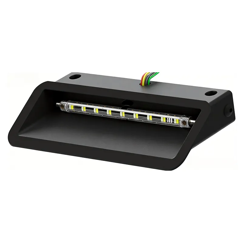
Table of Contents
Click any topic to jump directly to the section.
- 1. What Is the Real Purpose of Vehicle Warning Illumination?
- 2. How Does LED Technology Improve Warning Performance?
- 3. Which Warning Light Configurations Are Available?
- 4. How Should Warning Light Color Be Selected?
- 5. Why Do Optics, Flash Patterns, and Viewing Angles Matter?
- 6. Where Should Warning Lights Be Mounted?
- 7. Which Environmental Conditions Should Be Considered?
- 8. How Do Electrical Systems and Controllers Affect Operation?
- 9. How Can Warning Systems Be Integrated Into Different Vehicles?
- 10. How Should Compliance and Testing Be Evaluated?
- 11. What Are the Most Common Selection Mistakes?
- 12. How Can Manufacturers Improve System Reliability?
- 13. What Should a Practical Technical Specification Include?
- 14. Frequently Asked Questions
What Is the Real Purpose of Vehicle Warning Illumination?
Warning illumination is fundamentally a visual communication system. Its job is to attract appropriate attention and help surrounding people understand that a vehicle has a special operating condition.
A warning signal may indicate that a vehicle is responding to an emergency, working beside a roadway, moving slowly, servicing infrastructure, operating in a temporary work area, towing equipment, or performing another task that requires additional awareness from people nearby.
This makes warning illumination different from ordinary vehicle lighting. Headlamps, brake lamps, turn signals, and marker lamps primarily communicate normal vehicle functions. A warning system adds another layer of information about the vehicle’s status or operating environment.
The distinction becomes particularly important when a vehicle operates across several environments. A utility truck may travel through a city during the day, stop beside a road in the evening, enter a construction area, and work close to pedestrians or machinery. The same physical vehicle may therefore require visibility from several directions under very different background lighting conditions.
The system should help nearby people recognize that the vehicle has a special operating condition.
Light distribution should make the vehicle visible from the angles that matter in the actual work environment.
Repeatable patterns and clear controls help operators use the warning system predictably.
The warning equipment should work with the vehicle structure, electrical system, controls, and other installed components.
One of the most common misunderstandings is that warning performance is simply a question of brightness. In reality, useful visibility depends on brightness, viewing angle, background contrast, flash behavior, lens design, mounting height, vehicle geometry, weather, and the visual environment surrounding the vehicle.
A very bright module mounted behind an obstruction may produce less useful warning coverage than a moderately powerful system positioned correctly around the vehicle. Likewise, a signal that looks impressive in a dark workshop may behave differently in sunlight, heavy rain, fog, dust, or an environment containing multiple bright light sources.
How Does LED Technology Improve Warning Performance?
LED technology has transformed the design of vehicle warning products. Solid-state LEDs allow manufacturers to build compact modules with flexible optical arrangements, electronic control, and highly integrated housings.
The flexibility of LED placement is one of the most important advantages. Multiple emitters can be arranged behind a lens, along a bar, within a compact lighthead, or across several distributed modules. This enables designers to create warning patterns that are matched to specific viewing angles rather than treating the lamp as a single point source.
Compact product architecture
LED modules can be designed in relatively small packages, making it possible to integrate warning functions into grilles, bumpers, mirrors, side panels, roof assemblies, visor areas, and other constrained locations. This is useful for modern vehicles where exterior styling, aerodynamic requirements, and equipment integration all matter.
Electronic flash control
LEDs can be switched electronically with precise timing. This supports multiple flash patterns, synchronized operation, alternating sequences, directional functions, and other controlled behaviors.
Electronic control also makes it easier to coordinate several modules. For example, front and rear products can operate together while side modules create additional coverage at lateral angles.
Durability of solid-state construction
LED products do not rely on a traditional filament inside the light source. That changes the construction of the lamp and can reduce sensitivity to certain types of mechanical failure associated with filament-based light sources.
Thermal design remains important
LED technology still produces heat. Although LED systems are efficient, their internal temperature affects electronic and optical behavior. Housing design, heat dissipation, installation location, ambient temperature, and operating duration can all influence thermal performance.
| Technology Area | What It Influences | Practical Consideration |
|---|---|---|
| LED emitter layout | Output and optical coverage | Match emitter arrangement to the required viewing angles |
| Optical lens | Beam shape and distribution | Review the actual coverage rather than output alone |
| Housing | Protection and thermal behavior | Match enclosure design to the installation environment |
| Control electronics | Patterns and synchronization | Use clearly defined operating modes |
The important point is that LEDs are a technology platform, not a complete warning solution by themselves. Optical design, electronics, thermal management, housing construction, mounting, and control logic determine how effectively that technology performs on an actual vehicle.
Which Warning Light Configurations Are Available?
Modern vehicle warning systems are available in several physical forms. Each configuration is designed around a different installation requirement, and professional vehicles often combine several types to achieve broader coverage.
Roof-mounted lightbars
Lightbars are typically installed across the roof and can contain multiple optical modules arranged to provide forward, rearward, and side coverage.
Their elevated position can help the warning signal remain visible above other vehicle structures. However, the roof mounting position also exposes the product to wind load, weather, vibration, and increased overall vehicle height.
Compact lightheads
Lightheads are smaller individual modules that can be distributed around the vehicle. They are often used in grille openings, bumpers, side panels, rear bodywork, mirror areas, or other locations where a large lightbar is not practical.
Distributed lightheads can be particularly useful for closing visibility gaps created by bodywork or equipment.
Beacons
Beacons are usually positioned at an elevated point and provide a highly recognizable warning signal. Their cylindrical or compact form allows them to be mounted on vehicle roofs, equipment structures, or specialty platforms.
Hideaway systems
Hideaway modules are installed behind existing vehicle structures, allowing the warning function to remain visually discreet when not operating. Installation requires careful consideration of optical clearance, heat dissipation, wiring, and service access.
Visor-mounted systems
Visor units are installed inside the vehicle near the upper windshield area. They can provide forward warning illumination while maintaining a compact installation footprint.
The main issue is ensuring that the system does not create excessive reflections or interfere with the operator’s visibility.
Directional warning systems
Directional systems use controlled sequences to communicate left, right, or center movement. They are especially relevant to roadside service vehicles, traffic management vehicles, recovery trucks, and work vehicles operating around active traffic areas.
| Configuration | Typical Installation | Main Advantage | Main Consideration |
|---|---|---|---|
| Lightbar | Roof | Broad elevated visibility | Mounting, height, wind exposure |
| Lighthead | Grille, bumper, side, rear | Flexible distributed placement | Optical direction and available installation depth |
| Beacon | Elevated mounting position | Distinctive high-level warning signal | Mounting strength and overall vehicle height |
| Hideaway | Behind vehicle panels | Discreet integration | Clear optical path and thermal management |
| Visor unit | Interior upper windshield | Compact forward warning | Driver visibility and reflections |
| Directional unit | Rear or service area | Traffic-direction communication | Control sequencing and synchronization |
There is no single configuration that fits every vehicle. Selection should begin with the visibility problem that needs to be solved and then identify which physical arrangement can address that problem most effectively.
A large work truck may use an elevated lightbar together with front and rear lightheads, while a compact service vehicle may rely primarily on discreet grille and rear modules. The important factor is coverage, not simply product quantity.
How Should Warning Light Color Be Selected?
Warning color carries information, but the correct color depends on the vehicle role, country, jurisdiction, service category, and applicable regulations.
Common warning colors include amber, red, and blue. Different vehicle classes may also use multi-color configurations for different operating states. Because these rules can vary, color should always be treated as a regulatory and functional decision rather than a purely visual preference.
Amber warning systems
Amber is widely associated with caution, work activity, roadside operations, maintenance, construction, utility services, slow-moving equipment, and other applications where increased attention is required.
Red warning systems
Red can carry strong warning significance and may be associated with particular vehicle functions or authorized service categories depending on the jurisdiction.
Blue warning systems
Blue is often subject to stricter controls and may be reserved for particular emergency or authorized vehicle categories. Its suitability should therefore be checked carefully for the destination market and vehicle role.
Dual-color systems
Dual-color products can support different operating states. For example, one approved color may be associated with general work activity while another is used for a separate operational function. Controller logic should make these modes clear and prevent accidental combinations.
| Color Strategy | Potential Application | Important Consideration |
|---|---|---|
| Amber | Work, caution, service, roadside activity | Common in work-related applications, subject to local rules |
| Red | Designated warning functions | Use according to vehicle and jurisdiction requirements |
| Blue | Specialized emergency signaling | Often more tightly regulated |
| Dual color | Multiple operational states | Controller logic should clearly separate approved modes |
Color also interacts with the environment. The visual contrast between the warning signal and its background can change under sunlight, nighttime conditions, urban lighting, snow, fog, or reflective surfaces.
Why Do Optics, Flash Patterns, and Viewing Angles Matter?
Warning visibility depends heavily on optical design. The surrounding road user may see the vehicle from directly ahead, from an angle, from the side, or from behind. The warning system must therefore provide meaningful visibility across the directions that matter.
Beam distribution
Optical lenses, reflectors, LED arrangement, module orientation, and housing geometry determine how the emitted light spreads. A forward-facing light is optimized differently from a module intended to provide broad lateral coverage.
A practical system should minimize unnecessary weak zones. This is why light distribution needs to be evaluated across the relevant viewing angles rather than only from one preferred direction.
Viewing angle
Vehicle bodywork can create unexpected optical obstructions. A grille-mounted unit may work very well from the front while providing limited visibility from a side angle. A roof bar may offer broad coverage but still leave gaps close to the vehicle.
Mapping the vehicle from multiple viewpoints before installation can reveal these areas.
Flash patterns
Flashing makes warning illumination visually distinct from many ordinary vehicle lights. Different patterns can support different operating states or create greater visual separation from the background.
However, excessive pattern complexity can create another problem. Operators may have difficulty remembering which pattern corresponds to a particular function. A smaller set of clearly defined modes can often be more practical than an unnecessarily large pattern library.
Synchronization
When several modules operate as one system, synchronization affects the overall visual result. Modules may flash simultaneously, alternate between left and right, sweep across the vehicle, or operate in separate synchronized groups.
Multiple modules activate together to create a unified warning event.
Separate groups activate in sequence to create visual movement across the vehicle.
Light activity travels through an arranged group and can support directional functions.
Approved patterns can be selected according to the vehicle’s operating state.
Real-world visual conditions
Optical performance should be considered under realistic conditions. Bright sunlight, headlights, wet pavement, fog, dust, reflective signs, snow, and nearby work lights can alter the way warning signals are perceived.
This is why laboratory output alone does not tell the entire story. The final vehicle installation determines whether the light actually reaches the viewer in a useful form.
Where Should Warning Lights Be Mounted?
Mounting position has a direct influence on visibility. It determines elevation, line of sight, obstruction, cable routing, mechanical stress, and accessibility for maintenance.
Roof mounting
Roof-mounted systems benefit from elevation. They can remain visible above many vehicle structures and can provide broad forward, rearward, and lateral coverage.
At the same time, roof installation increases exposure to wind, rain, snow, vehicle washing, and accidental impact. Mounting hardware must therefore be appropriate to the roof structure and vehicle operating environment.
Front grille mounting
Grille-mounted lightheads can provide lower-level frontal warning coverage and can complement a roof-mounted product. Installation depth and optical clearance should be reviewed carefully.
Rear mounting
Rear warning modules can be particularly important for roadside service and utility vehicles that stop or work along public roads. A following driver may not be able to see a front or roof-mounted light clearly if the vehicle body or nearby equipment blocks the signal.
Side mounting
Side modules can reduce lateral visibility gaps. This can be valuable when vehicles work around intersections, pedestrians, machinery, or passing traffic.
Concealed integration
Hideaway modules can preserve a clean exterior appearance while providing warning functionality. These installations require careful consideration of the surrounding material and the optical path.
| Mounting Position | Main Visibility Role | Typical Challenge |
|---|---|---|
| Roof | Elevated broad coverage | Wind load, height, mounting strength |
| Front grille | Forward and diagonal coverage | Body obstruction and installation depth |
| Rear | Following traffic | Doors, equipment, racks, and bodywork |
| Side | Lateral coverage | Vehicle geometry and module orientation |
| Visor | Forward cabin visibility | Reflections and driver visibility |
A useful design method is to create a visibility map. Mark the vehicle’s front, rear, side, elevated, and close-range viewing zones, then identify which areas are blocked by mirrors, equipment, body panels, rails, ladders, racks, or attachments.
Once those gaps are known, each warning module has a clear job. This approach is more effective than adding lights randomly until the vehicle appears sufficiently bright.
Which Environmental Conditions Should Be Considered?
Vehicle warning equipment operates in environments that can be considerably harsher than indoor electrical applications. Outdoor exposure can include rain, road spray, snow, mud, dust, vibration, ultraviolet radiation, temperature changes, cleaning chemicals, and mechanical impact.
Water exposure
Outdoor warning products should have enclosure protection appropriate to their intended installation. Water can enter through seams, connectors, cable exits, mounting interfaces, or damaged seals.
Installation quality is part of the water-protection equation. An enclosure can be well sealed at the factory and still experience water entry if cable routing, mounting holes, or connector placement are handled incorrectly during installation.
Dust and mud
Construction, agricultural, mining, forestry, and industrial vehicles can operate in environments containing dust, mud, sand, and fine particles. Lenses should remain practical to clean, and the installation should avoid unnecessarily exposed locations where contamination can accumulate.
Vibration and shock
Vehicle movement subjects warning products to mechanical vibration. Uneven roads, off-road operation, heavy equipment, and frequent vehicle movement can place stress on brackets, fasteners, circuit boards, connectors, and internal components.
Temperature
Vehicles may be parked in direct sunlight or operated during cold winter conditions. The product should therefore be selected for the actual operating temperature range, especially where continuous or frequent flashing is expected.
UV exposure
Outdoor lenses and housings may be exposed to prolonged ultraviolet radiation. Material selection should consider resistance to yellowing, cracking, embrittlement, and loss of optical clarity over time.
- Water protection: Match the enclosure and installation method to the actual exposure.
- Mechanical durability: Consider vibration, impact, shock, and mounting stress.
- Thermal behavior: Confirm operation within the expected temperature range.
- UV resistance: Consider long-term outdoor exposure of lenses and housings.
- Connector protection: Protect cable entries and electrical interfaces as carefully as the lamp housing.
Environmental ratings should be interpreted together with the final installation. A product rating is only meaningful when the installed configuration preserves the conditions for which the product was designed.
How Do Electrical Systems and Controllers Affect Operation?
Modern warning systems often contain multiple lightheads controlled as a coordinated network rather than one independent lamp connected to a switch.
Voltage compatibility
Vehicle electrical systems vary by application. The warning equipment must therefore be matched to the vehicle’s nominal voltage and operating range.
Voltage compatibility should be checked before installation rather than assumed from the vehicle category.
Circuit protection
Appropriate wiring, fusing, grounding, cable sizing, connector selection, and circuit protection are important for safe electrical integration.
The wiring system should also be protected from abrasion, excessive heat, moving components, water exposure, and mechanical stress.
Controller functions
Depending on the product design, a controller may manage flash patterns, synchronization, color modes, directional sequences, power switching, or several groups of light modules.
| Control Function | Purpose | Practical Requirement |
|---|---|---|
| Power control | Enable or disable the warning system | Clear operator identification |
| Pattern selection | Select approved flash behavior | Simple and logical mode arrangement |
| Color control | Change approved operating color or mode | Prevent accidental inappropriate combinations |
| Directional control | Create left, right, or center sequences | Clear relationship between input and output |
| Synchronization | Coordinate multiple modules | Stable timing across the system |
Simple controls are often more practical
A control panel with many buttons is not automatically better. Operators may need to activate warning functions while wearing gloves, working at night, or concentrating on vehicle operation.
Clearly labeled controls and logical grouping can make the system easier to use under real operating conditions.
Service access
The controller should be protected from unnecessary heat, water, and impact while remaining accessible for maintenance. Cable harnesses should be labeled so technicians can identify modules and circuits without unnecessary dismantling.
How Can Warning Systems Be Integrated Into Different Vehicles?
Every vehicle presents a different warning problem. Body dimensions, equipment, operating speed, work environment, and regulatory requirements can change the appropriate configuration significantly.
May require coordinated warning coverage, rapid mode selection, controlled flash patterns, and strong visibility from multiple directions.
Often require warning coverage around large equipment structures and protection against dust, vibration, mud, and physical impact.
May frequently stop beside roads or infrastructure, making rear and lateral recognition important.
May operate around large attachments and in changing light conditions, requiring thoughtful placement and durable construction.
Can encounter branches, uneven terrain, dust, vibration, and low-light conditions that place additional demands on mounting and housing design.
Often works close to moving traffic, making fast recognition from approaching and passing directions especially important.
Fleet vehicles
Fleets may include different vehicle models with different roofs, grilles, electrical systems, and body dimensions. A standardized warning strategy should therefore define common functional requirements while allowing physical configurations to adapt to each vehicle.
Construction and heavy equipment
Heavy equipment can have large blind areas. Warning modules may need to be positioned above cabins, around machine bodies, or near rear structures. Mounting hardware should be selected for the vibration and movement associated with the machine.
Agricultural applications
Agricultural equipment may transition between field work and road travel. Warning equipment may therefore need to remain visible around large attachments and moving components while surviving dust, mud, sunlight, moisture, and long operating periods.
Specialty vehicles
Service, recovery, transport, and municipal vehicles may require a customized combination of lightbars, beacons, lightheads, directional systems, and controllers. In such cases, application-specific integration is usually more appropriate than relying on one generic product arrangement.
Across all of these applications, the best system begins with the vehicle's operating scenario rather than with a product catalog.
How Should Compliance and Testing Be Evaluated?
Vehicle warning equipment can be subject to market-specific regulations, photometric requirements, electromagnetic compatibility requirements, environmental testing, and vehicle-category rules.
Terms and standards appearing on technical documents should therefore be interpreted carefully. A particular designation may address optical performance, electromagnetic compatibility, or another part of the product requirement. Different designations should not be treated as interchangeable.
Photometric testing
Photometric evaluation examines optical behavior and can include output, distribution, color, and visibility over defined angles depending on the applicable requirement.
Vibration testing
Vehicle lighting is continuously exposed to vibration. Testing can help evaluate the durability of the housing, mounting structure, electrical connections, circuit boards, optical components, and internal assemblies.
Water and ingress testing
Outdoor warning equipment should be evaluated for the relevant environmental exposure. The necessary protection depends on the location of installation and the conditions expected during use.
Corrosion evaluation
Road salt, humidity, water, and industrial contaminants can affect metal surfaces, coatings, fasteners, and mounting structures. Corrosion testing can help identify weaknesses in materials and surface treatment.
Electromagnetic compatibility
Warning equipment operates alongside radios, navigation systems, control modules, engine electronics, sensors, and other vehicle systems. Electromagnetic compatibility is therefore an important consideration for integrated vehicle electronics.
| Test Area | Primary Focus | Why It Matters |
|---|---|---|
| Photometric | Optical output and distribution | Helps verify visibility and signal behavior |
| Vibration | Mechanical durability | Simulates stresses from vehicle movement |
| Water ingress | Enclosure protection | Important for outdoor and exposed installation |
| Corrosion | Material and finish resistance | Relevant to salt, moisture, and industrial environments |
| EMC | Electrical compatibility | Supports stable operation alongside other vehicle electronics |
Compliance should also be considered at the configuration level. A test result may apply to a particular product arrangement, color, mounting orientation, or operating mode. Technical documentation should make those conditions clear.
What Are the Most Common Selection Mistakes?
Many warning-system problems originate during selection rather than after installation. The most common mistakes involve focusing on appearance or brightness while overlooking vehicle geometry, legal requirements, environmental exposure, or control architecture.
- Choosing only by brightness: Output alone does not determine useful coverage.
- Ignoring mounting position: Bodywork or equipment can block a well-designed lamp.
- Using an inappropriate color: Color requirements vary by application and jurisdiction.
- Ignoring the controller: Multiple light modules need coordinated operating logic.
- Overlooking environmental exposure: Dust, mud, salt, vibration, and temperature affect product selection.
- Blocking service access: Hidden equipment becomes difficult to inspect and replace.
- Mixing incompatible components: Voltage, connectors, controller architecture, and mounting dimensions need to match.
- Adding too many modules: More products do not automatically solve a poor visibility strategy.
The brightness-only problem
A warning system that looks extremely bright from one direction may still produce weak lateral or rear coverage. The complete viewing envelope should therefore be considered.
The one-product-fits-all problem
A roof lightbar that works well on one truck may be inappropriate for a compact service vehicle. Likewise, a grille lighthead may be ideal for one body shape and poorly suited to another.
The legal-color problem
Color should be confirmed for the destination market and vehicle role before installation. A product being physically capable of producing a specific color does not automatically make that color suitable for every application.
The maintenance problem
Warning systems are often installed in difficult locations because the most visible mounting points are not always the easiest to service. Installation should balance visibility with reasonable access for inspection, cleaning, and replacement.
How Can Manufacturers Improve System Reliability?
Reliable warning equipment depends on the coordinated quality of LEDs, circuit boards, optical lenses, housings, seals, connectors, wiring, mounting hardware, and controller components.
Optical assembly control
Emitter positioning and lens alignment can influence optical uniformity. When several modules are installed next to one another, small differences in optical behavior can become more visible.
Electrical assembly control
Wiring, solder joints, connectors, circuit protection components, and printed circuit boards should be assembled according to controlled manufacturing procedures.
Mechanical assembly control
Fasteners, brackets, seals, cable exits, and lens interfaces should be installed consistently. Vehicle vibration places repeated mechanical stress on these components.
Process inspection
Quality inspection is stronger when it is distributed throughout manufacturing instead of being limited to a final cosmetic check.
- Inspect incoming components: Verify critical LEDs, electronics, lenses, housings, seals, and connectors.
- Control assembly: Use repeatable procedures for wiring, soldering, sealing, fastening, and lens installation.
- Check optical behavior: Verify approved light patterns and optical output.
- Evaluate environmental resistance: Apply relevant water, vibration, corrosion, and temperature tests.
- Verify controller operation: Confirm patterns, colors, synchronization, and directional functions.
- Inspect the finished assembly: Check connectors, mounting points, lens condition, enclosure quality, and labeling.
Why consistency matters in fleet applications
A fleet may install dozens or hundreds of warning modules across different vehicle platforms. Consistent optical behavior, controller logic, connectors, mounting methods, and documentation can make installation and maintenance much easier.
Documentation as part of quality
Technical drawings, wiring diagrams, installation instructions, controller information, and inspection records help create a clear connection between manufacturing and vehicle integration.
Good documentation also supports future maintenance. A technician should be able to identify which module connects to which controller output and understand the intended operating mode without reverse-engineering the entire vehicle.
What Should a Practical Technical Specification Include?
A practical technical specification turns a general warning-light requirement into a configuration that designers, manufacturers, installers, and operators can understand consistently.
| Specification Area | Information to Define | Why It Matters |
|---|---|---|
| Vehicle role | Emergency, construction, utility, agricultural, transport, service, or specialty use | Establishes the operating context |
| Configuration | Lightbar, beacon, lighthead, hideaway, visor, directional system | Determines physical and optical integration |
| Color | Approved warning color or combination | Connects the system to application requirements |
| Voltage | Vehicle electrical architecture and operating range | Prevents electrical mismatch |
| Control | Patterns, synchronization, directional modes, color control | Defines system behavior |
| Mounting | Roof, grille, rear, side, visor, concealed installation | Determines visibility and installation requirements |
| Environment | Water, dust, vibration, temperature, UV, corrosion | Matches construction to operating conditions |
| Testing | Applicable market and product test requirements | Provides a clear technical basis for evaluation |
Define the vehicle first
Vehicle dimensions, roof structure, body panels, grilles, equipment racks, mirrors, doors, attachments, and existing lights should be mapped before the warning layout is finalized.
Define actual operating conditions
The specification should identify where and when the system will be used. Daytime roadside work, nighttime construction, emergency response, agricultural field work, warehouse yards, and municipal service operations can require very different warning strategies.
Define visibility zones
Instead of only stating how many lamps are required, specify which directions must remain visible. A technical plan can identify front, rear, lateral, elevated, and close-range coverage requirements.
Define electrical architecture
Voltage, current requirements, connector type, controller location, circuit protection, cable routing, and grounding should be identified before production or vehicle conversion begins.
Define service requirements
Warning equipment should remain practical to clean, inspect, adjust, and replace. The technical specification should therefore include service access and installation details where appropriate.
Identify where approaching traffic, pedestrians, and workers need to see the vehicle.
Identify physical mounting points, obstructions, bodywork, and available space.
Identify power supply, controller location, cable routes, protection, and service access.
Identify how the product will be cleaned, inspected, adjusted, and replaced.
A practical selection workflow
- Define vehicle function: Establish the reason additional visual warning is required.
- Map viewing directions: Identify front, rear, side, elevated, and close-range visibility needs.
- Identify obstructions: Check bodywork, racks, mirrors, tools, attachments, and equipment.
- Select the physical configuration: Choose the appropriate combination of bars, beacons, and lightheads.
- Confirm color and patterns: Select approved operating modes for the destination and vehicle role.
- Confirm electrical compatibility: Check voltage, wiring, connectors, controller functions, and circuit protection.
- Confirm environmental requirements: Match the equipment to water, dust, vibration, UV, and temperature exposure.
- Review documentation: Ensure product drawings, wiring information, mounting details, and test documentation correspond to the final configuration.
This workflow keeps product selection tied to actual vehicle requirements. It also provides a clearer basis for communication between vehicle manufacturers, fleet operators, integrators, purchasing teams, and installation technicians.
Frequently Asked Questions
What are LED warning lights mainly used for?
They are used to increase vehicle visibility and communicate special operating conditions such as emergency response, roadside work, construction, maintenance, utility operations, traffic control, or other activities that require additional awareness.
Are all warning light colors suitable for every vehicle?
No. Warning-light colors can be regulated according to country, jurisdiction, vehicle category, and service type. The destination market and intended vehicle function should be confirmed before specifying a color.
What is the difference between a lightbar and a lighthead?
A lightbar is generally a larger multi-module assembly, often installed on a vehicle roof for broad coverage. A lighthead is a smaller individual module that can be distributed around the front, rear, side, or other body areas.
Why would a vehicle use several small modules instead of one large lightbar?
Distributed modules can fill visibility gaps caused by bodywork, equipment, or vehicle geometry. They can also make it easier to integrate warning functions into areas where a large roof assembly is not practical.
Does higher brightness always mean better warning performance?
No. Useful warning performance also depends on optical distribution, viewing angle, mounting position, background lighting, weather, vehicle geometry, and flash behavior.
Where should a warning light be installed?
The correct position depends on the vehicle and the directions from which it needs to be recognized. Roof, grille, rear, side, visor, and concealed positions all have different advantages and limitations.
What should be considered for construction vehicles?
Key considerations include vibration, dust, mud, impact exposure, equipment movement, mounting strength, visibility around large machine structures, wiring protection, and maintenance access.
How important is the controller?
The controller can coordinate multiple modules and manage approved flash patterns, synchronization, directional sequences, color modes, and switching functions. It is an important part of the overall warning system.
Why is environmental protection important?
Vehicle-mounted products can encounter rain, spray, dust, mud, salt, vibration, UV exposure, and temperature changes. The housing, lens, electrical connections, mounting hardware, and installation method should all be appropriate for the actual environment.
What kinds of testing should be considered?
Depending on the application and market, relevant evaluations may include photometric testing, vibration testing, water-ingress testing, corrosion assessment, temperature evaluation, electrical testing, and electromagnetic compatibility testing.
Can warning systems be customized for different vehicle models?
Yes. Customization can involve module size, mounting brackets, cable lengths, connectors, controller logic, flash patterns, color combinations, and physical installation arrangements.
How can a fleet standardize warning systems across different vehicles?
A fleet can establish common requirements for approved colors, operating patterns, controller logic, wiring practices, connectors, environmental protection, and inspection procedures while allowing the physical mounting configuration to vary by vehicle model.
What is the most important factor when selecting a warning system?
The most important factor is whether the complete system communicates the vehicle’s operating condition clearly under the conditions in which the vehicle will actually work. That requires considering application, viewing angles, mounting, optics, color, control, electrical compatibility, environmental protection, and applicable requirements together.
How Can Better Warning Design Create Clearer Vehicle Communication?
Effective vehicle warning illumination is the result of coordinated engineering rather than a single specification. LED technology provides a flexible foundation, but the final performance depends on optical design, color, flash behavior, mounting position, control logic, electrical integration, environmental protection, and the vehicle itself.
A roadside service truck may need strong rear and lateral recognition when stopped beside traffic. A construction machine may need elevated coverage around a large structure. Agricultural equipment may require warning visibility around attachments while working in changing weather. An emergency vehicle may require multiple coordinated modules with clearly defined operating modes.
These scenarios demonstrate why warning equipment should be planned as a system. Every module should have a reason for being installed. Every mounting position should address a visibility requirement. Every controller function should correspond to an operational need.
For fleet operators and vehicle integrators, this approach also makes standardization easier. Common requirements can be established for colors, patterns, controllers, wiring, mounting methods, environmental protection, and inspection while still allowing each vehicle platform to use a configuration suited to its own body structure.
For manufacturers, the same principle supports more useful customization. Instead of changing components without a defined purpose, a customized system can be developed around a specific vehicle role, mounting requirement, visibility zone, environmental condition, or control architecture.
Ultimately, well-engineered LED Warning Lights should make a vehicle easier to recognize and its operating condition easier to understand. The goal is not visual excess. The goal is dependable, clear, appropriately controlled communication between the vehicle and the people around it.
Need a Vehicle-Specific Warning Lighting Configuration?
NOVA provides vehicle warning lighting solutions for different operating environments, vehicle structures, mounting requirements, control systems, and application scenarios. For a configuration matched to your project requirements, contact us to discuss the technical details.